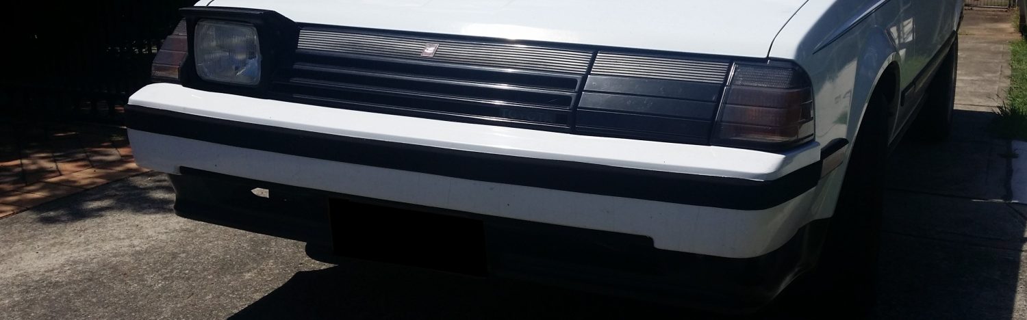
Chassis Wiring


I have started joining the Celica chassis harness to the 3SGE/Haltech harness I have already put together. The original engine didnt really have a harness, as there wasn’t much in the way of electronics. There was a few plugs, an 8 pin one that handled the reverse switch, temp and oil pressure sensors, and two that provided power to the igniton coil and tachometer. The alternator, starter and carburettor/emissions gear is wired straight to the body harness.
I need to modify the chassis wiring so that the starter and alternator can be plugged into the 3SGE harness. I also need to join the inputs on the chassis for sensors, switches and instrumentation to the outputs on the engine so the dash cluster is still functional. As the original ignition circuit isnt rated more than 10 amps, I will be adding additional circuits for the ECU, injectors, ignition and fuel pump.
Alternator

The new alternator has an onboard regulator so the wiring for the old alternator has to be changed. The S terminal senses the voltage at the battery. This is used to control the output voltage of the alternator. This connects to the W/BL wire on the 3SGE harness.
The L terminal runs the charge light in the dash cluster. This will light up if the voltage regulator detects a failure. IG is the signal wire to turn on the alternator. This will turn on when the key is in the start or run positions.
The B (White) was how the original alternator charged the battery, this wire is not used with the new alternator as it is connected directly to the positive battery terminal. As this wire is still needed to power some systems it will also be connected to the positive battery terminal.
Starting and ignition systems
Most of the original wiring for the igniton system has been removed, as it was only rated to 10A and I have fitted three 20A relay circuits to power the Ignition, ECU and fuel pump.

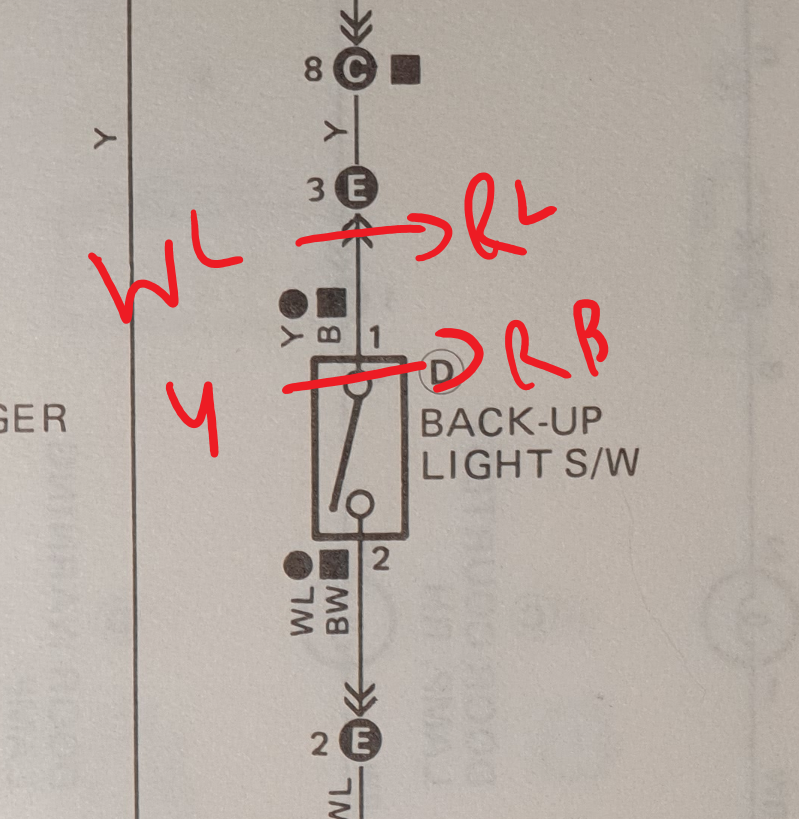
Signal wire on the 3SGE for the starter is B/Y. IG2 is the igniton circuit that powered the ignition coil and igniter on the 2S-C. The 3SGE reverse switch wiring (R/L & R/B), connects to WL & Y on the original 2SC sensor wiring
Sensors
Oil Pressure
The oil pressure switch is connected to AVI3 (O/R) on the Haltech, and also spliced into the oil pressure light on the dash. I have also wired in a plug for a three wire oil pressure sensor which uses connects to the 5V signal out on the Haltech, and is assigned input AVI4 (O/Y)
Tachometer
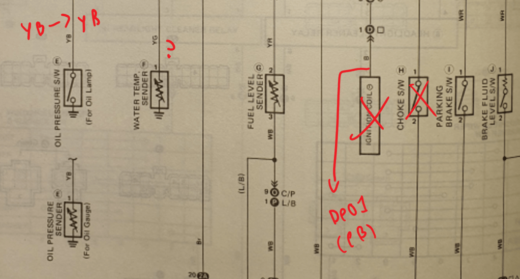
DPO1 on the Haltech is the output assigned to drive a tachometer. The tacho on the Celica dash cluster was driven by the voltage spike on the 2S-C coil when it fired. The DPO1 output on the Haltech is digital with a 0-5V range which will not work with the Celica tachometer. I will have to put together a circuit that can convert the signal but for now I have connected the tacho to DPO1, and will make a converter later on when the engine is running.
Water Temperature
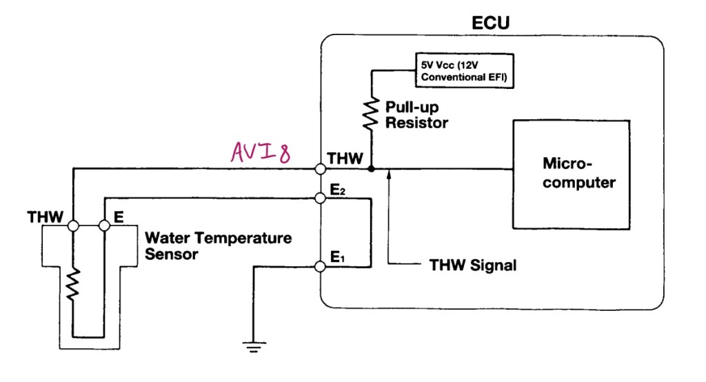

The water temperature sensor on the 3SGE is a negative temperature coefficient (NTC) thermistor. One of its main uses is changing the air-fuel ratio depending on coolant temperature which increases cold engine performance. As the sensor gets hotter the resistance decreases, giving a 0-5V range corresponding with temperature.
The original temperature sensor that drives the gauge on the Celica dash cluster is also the same type of thermistor. However, it is designed with a 0-12V range. When I tested it at -10C and 35C the values were 2500 and 450 ohms respectively, which is not in line with the values on the 3SGE sensor.
This means for the temperature gauge to work the original thermistor will have to be used. Until I find a suitable place to mount it the wire has been left disconnected.
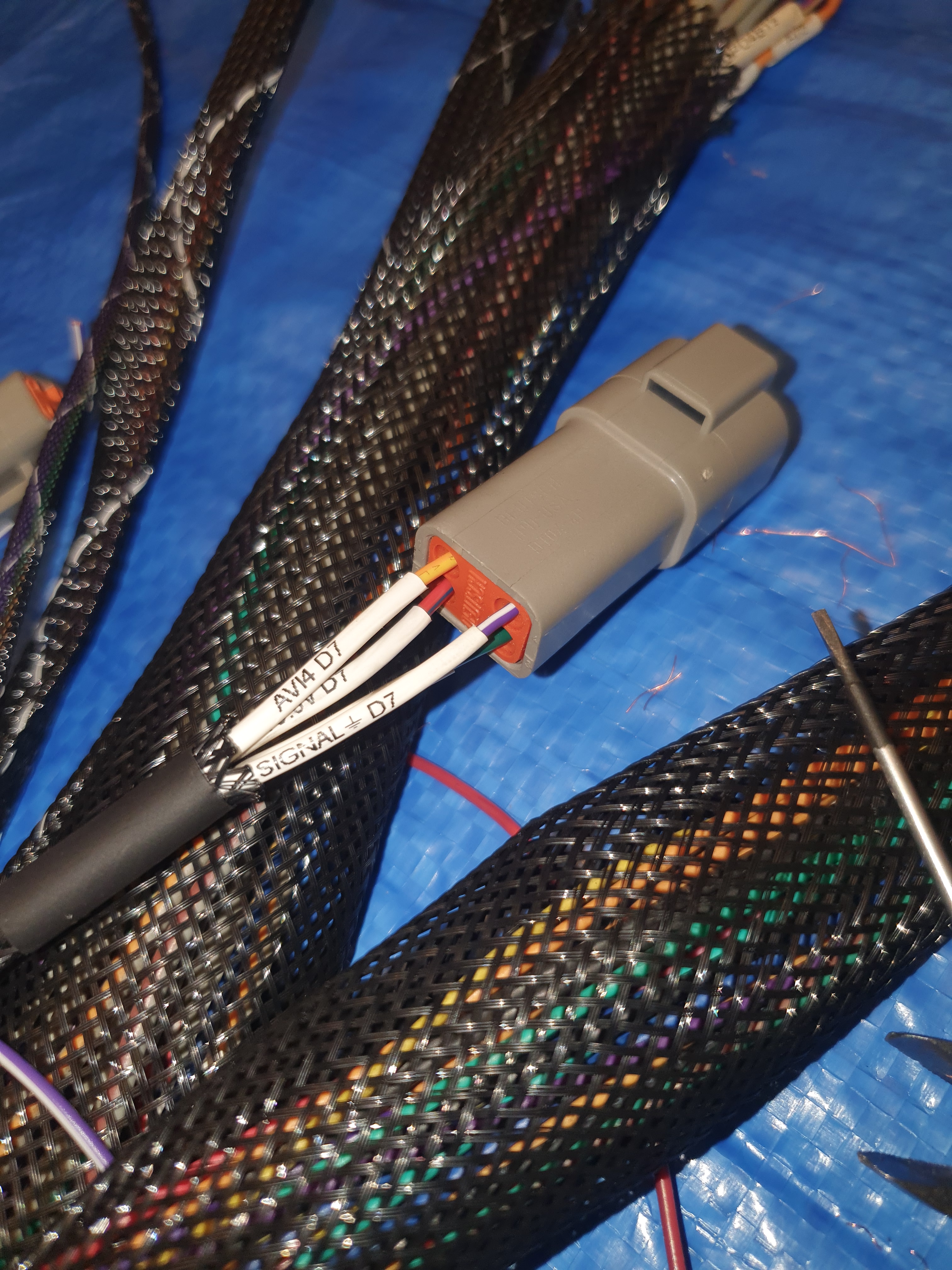
RA60 Chassis Wiring
As of 2022, the chassis harness looks like this:
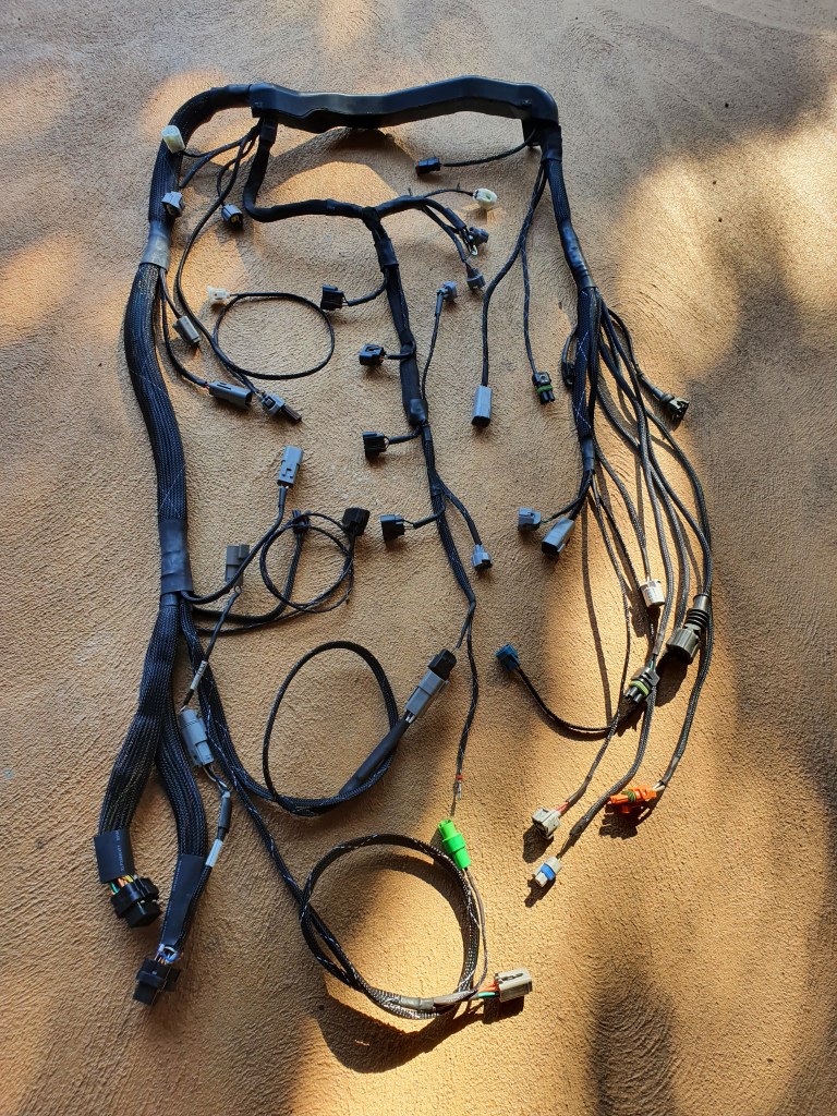
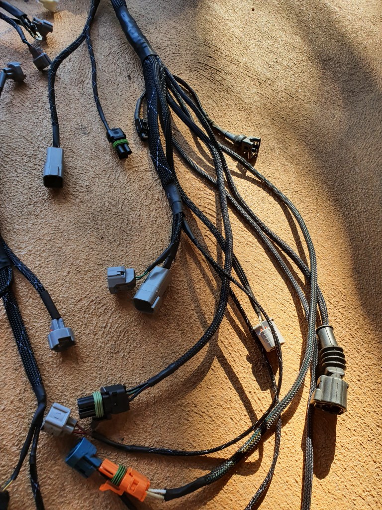
I wasnt happy with the old one so I started over. New denso plugs on igniton and injectors, and the layout has been improved significantly. every plug is routed where it needs to be, and ive upgraded them all to deutcsh/delphi plugs. i also added in three auxilary plugs for expansion, and integrated the wiring for the evap and original temp sensor

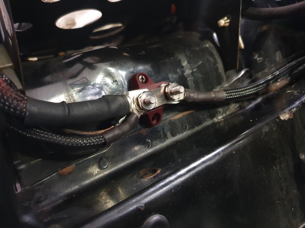
All of the engine bay wiring is also getting upgraded. Removed excess wiring, upgraded original connectors to waterproof ones. updated notes for each connectors pinouts, added a distribution block for the heavier gauge cables
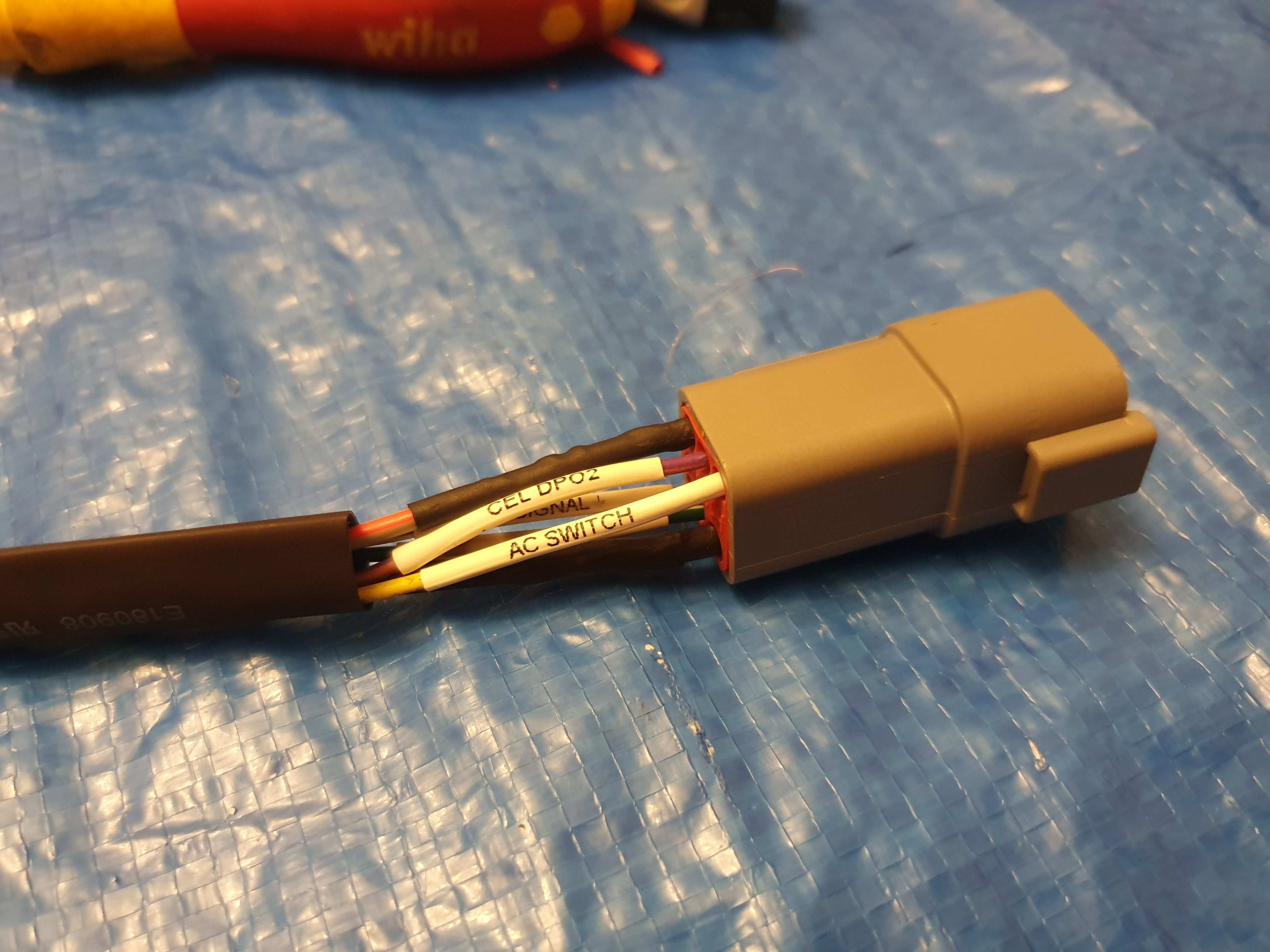
The unused ECU inputs have been assiged to auxilary plugs on the new harness. This way, adding new inputs is just plug and play.
detailed post on the complete harness coming soon
Related Posts:
Categories

Michael, good day .
I need some help on Toyota vvti system.
I use haltech 1500 , link DPO3 & SPI to vvti solenoid. But it look like no response.
Please share your experience.
Thank you very much
LikeLike