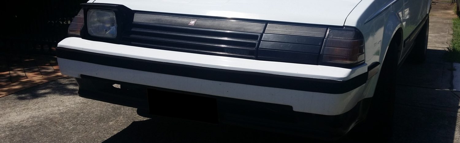
Chassis Swap


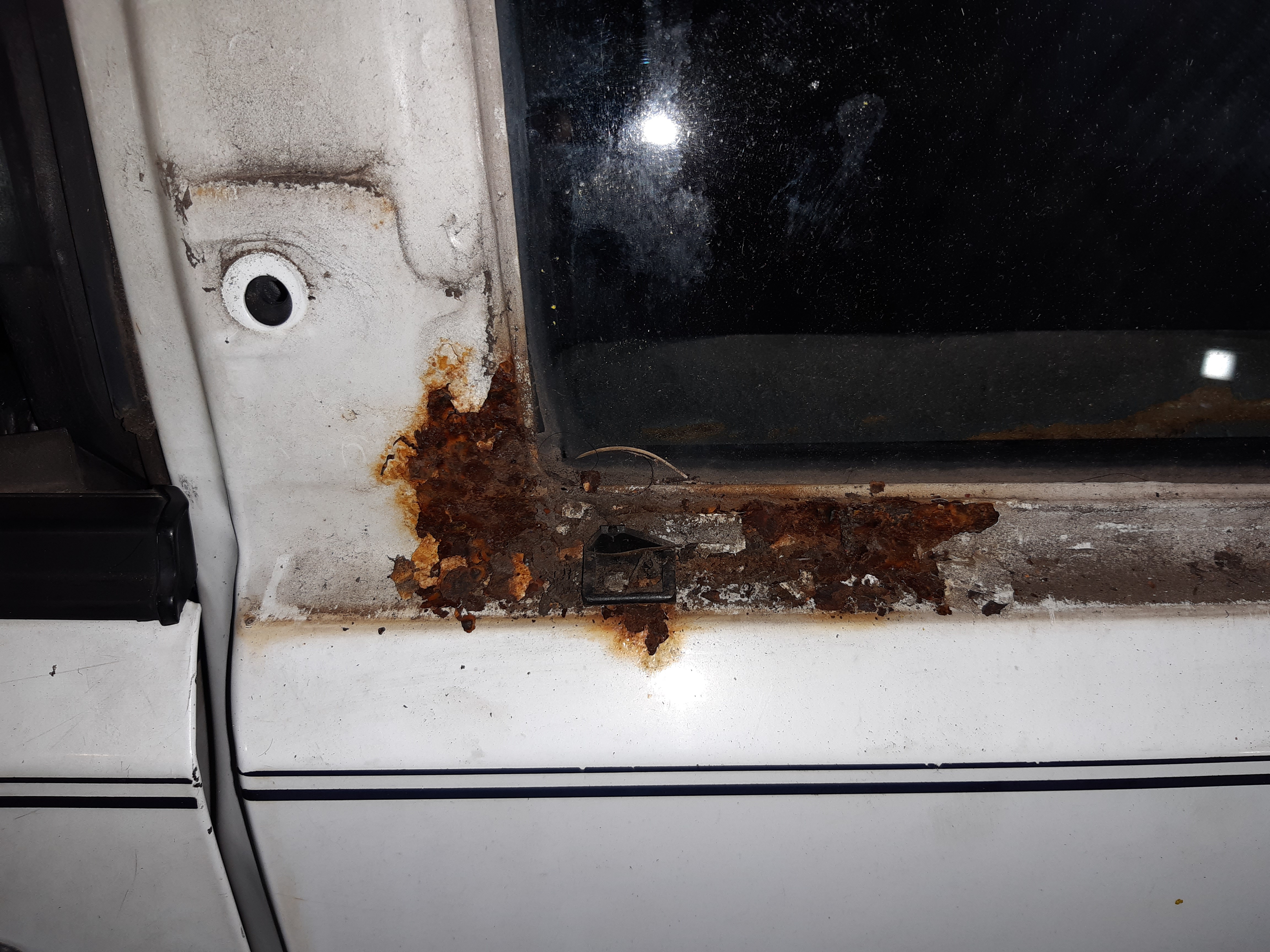
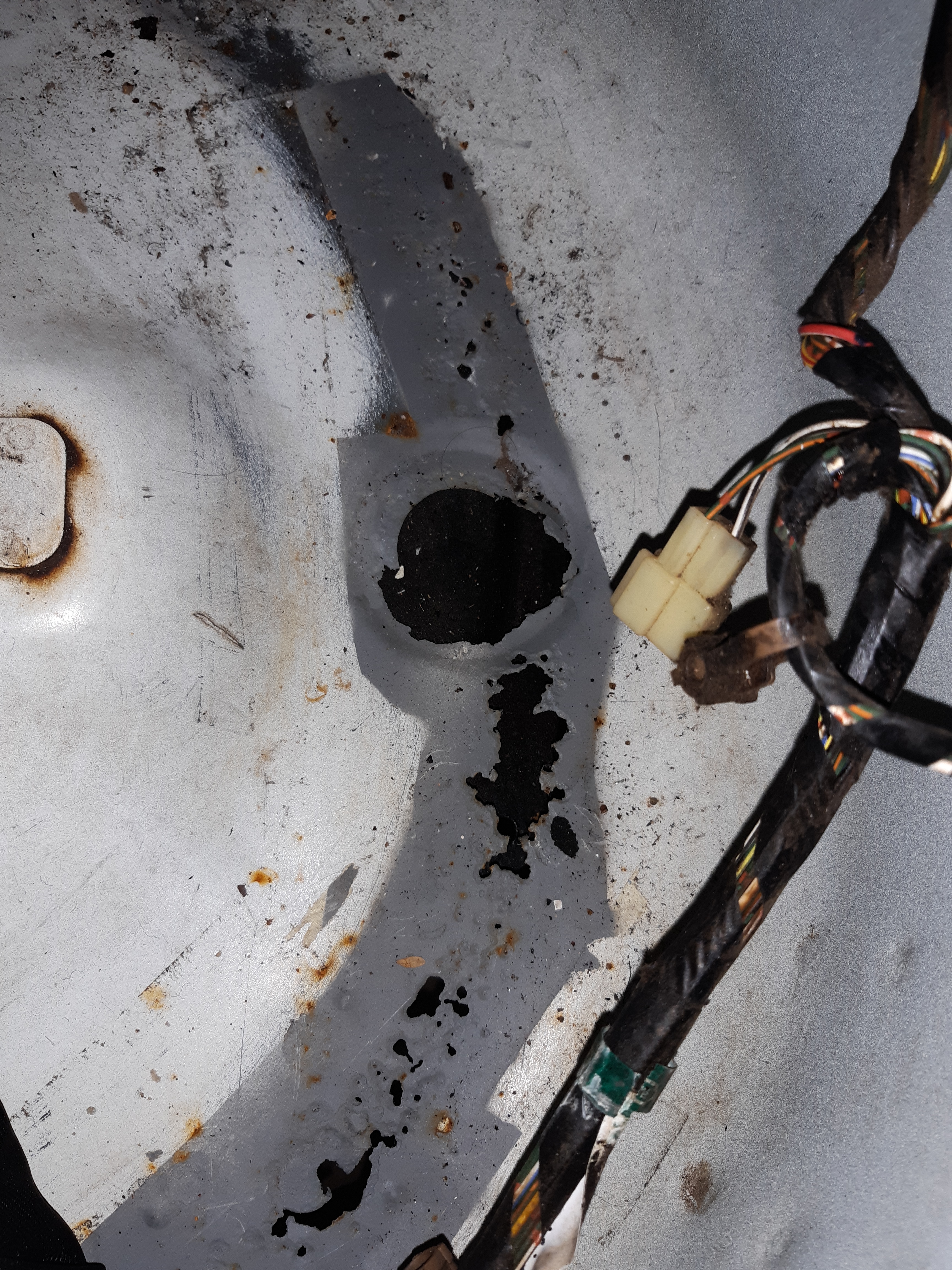
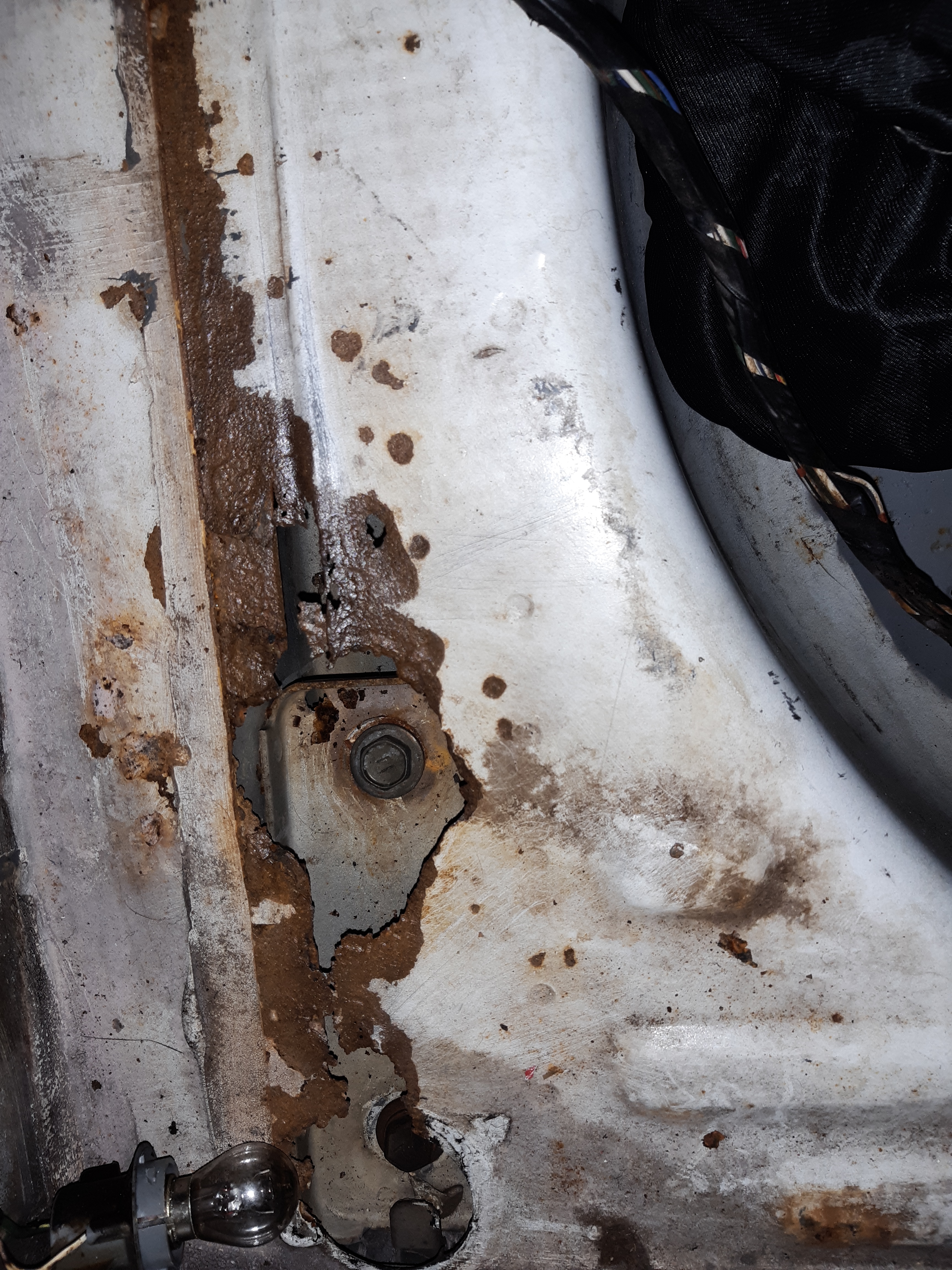
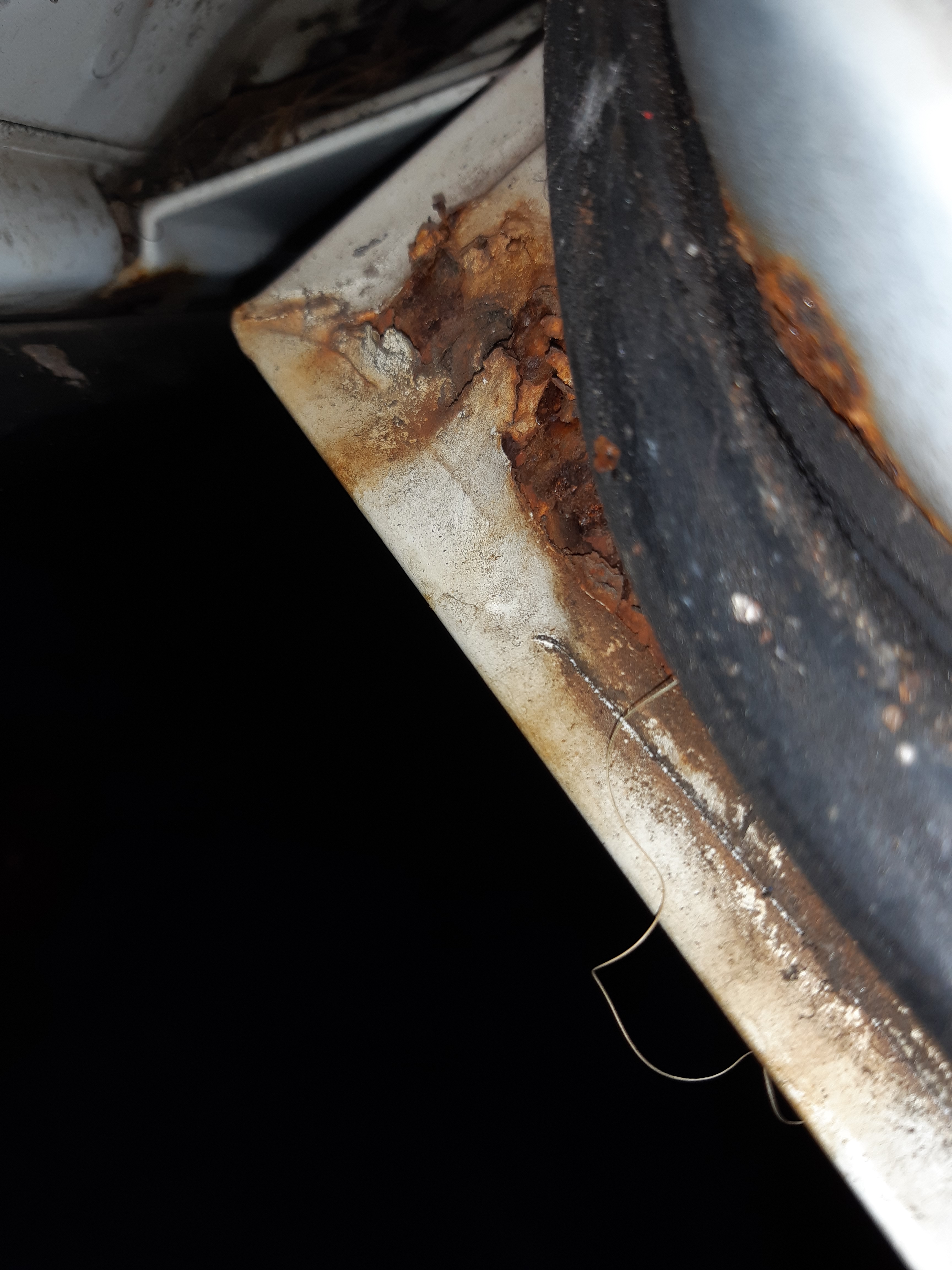
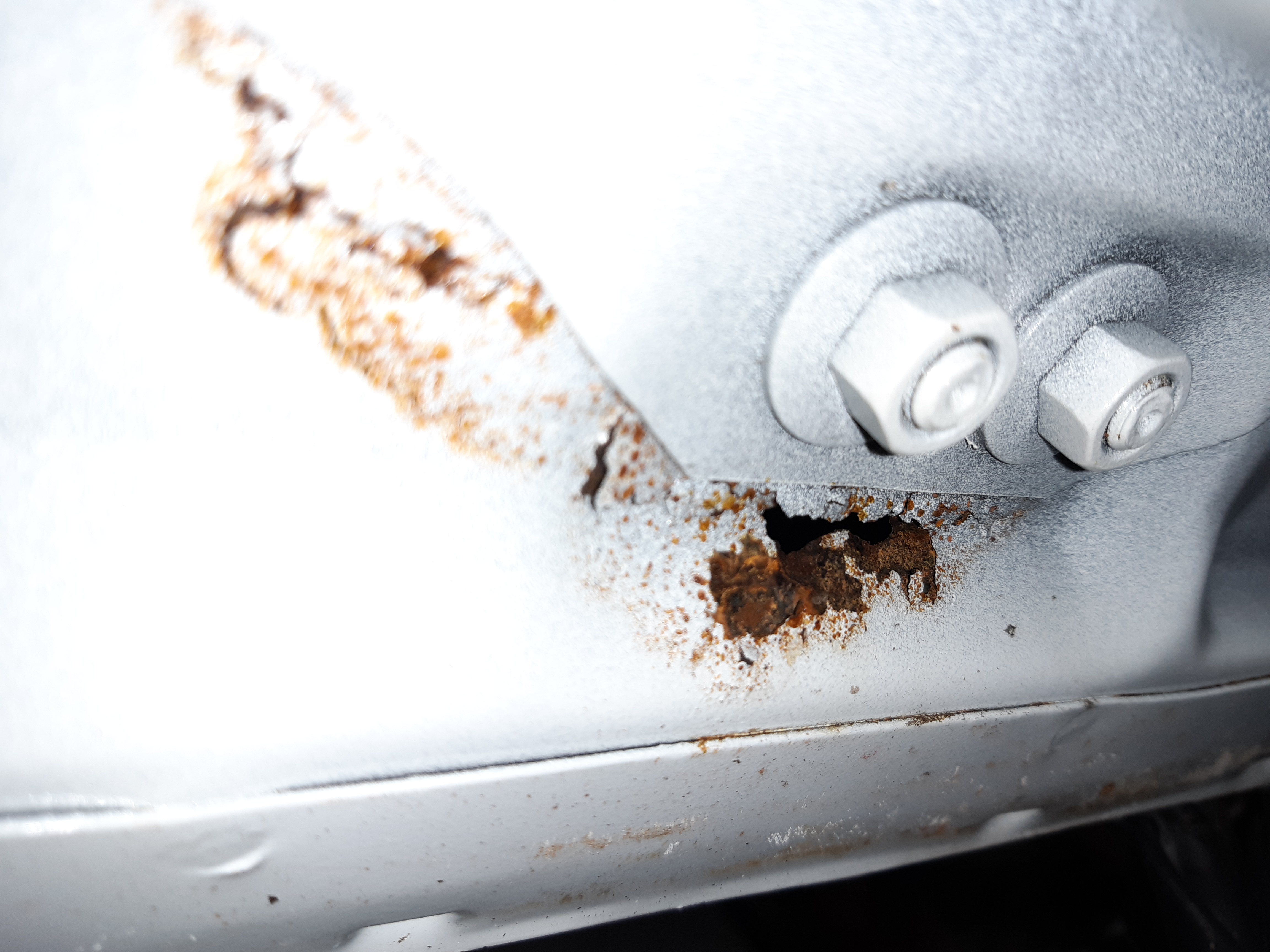

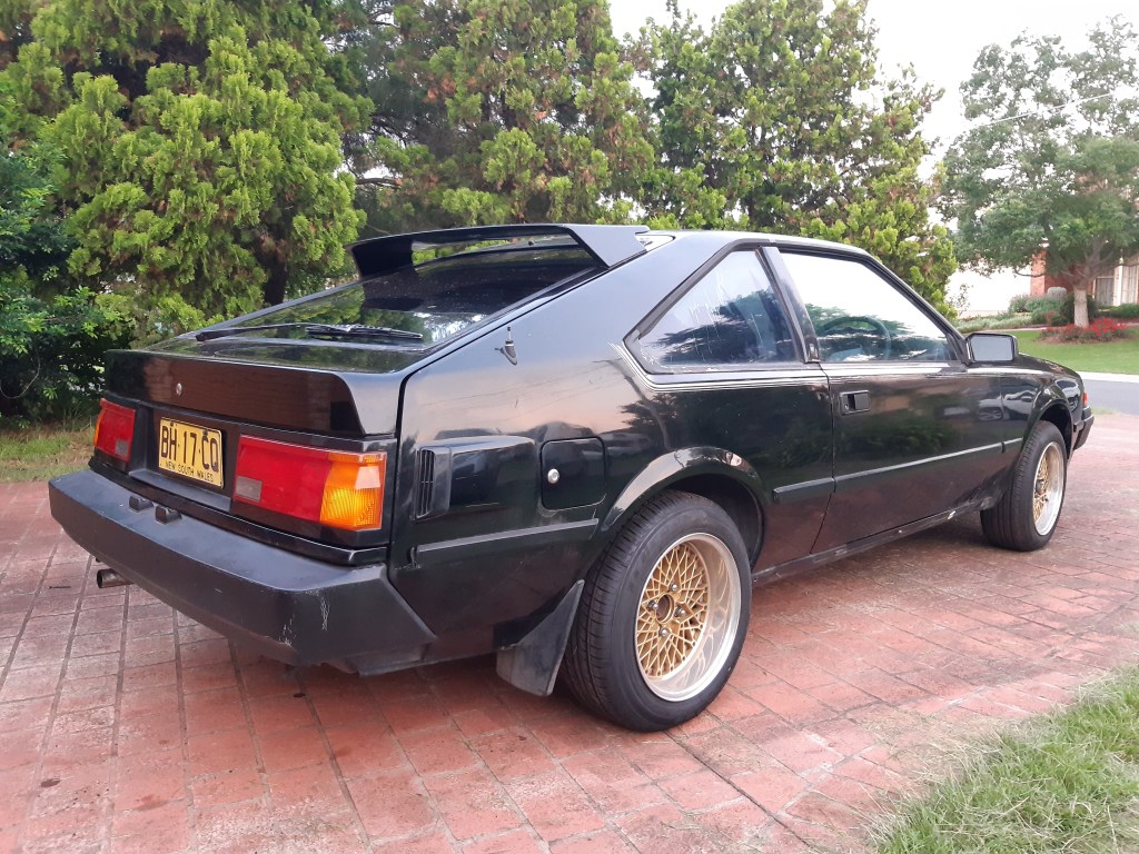
Now the engine is working I wanted to take a closer look at the rust on the car. After removing the window trims and roof lining I found the rust was worse than I thought. The entire rear section of the roof where the tailgate mounts has almost completely rusted through. I was aware of the issues with the wheel well and boot area but there is also several other spots, including a structural area under the front 1/4 panel. To get rust this severe repaired properly would cost more than the car is worth so I’m going to put it on the back burner for now
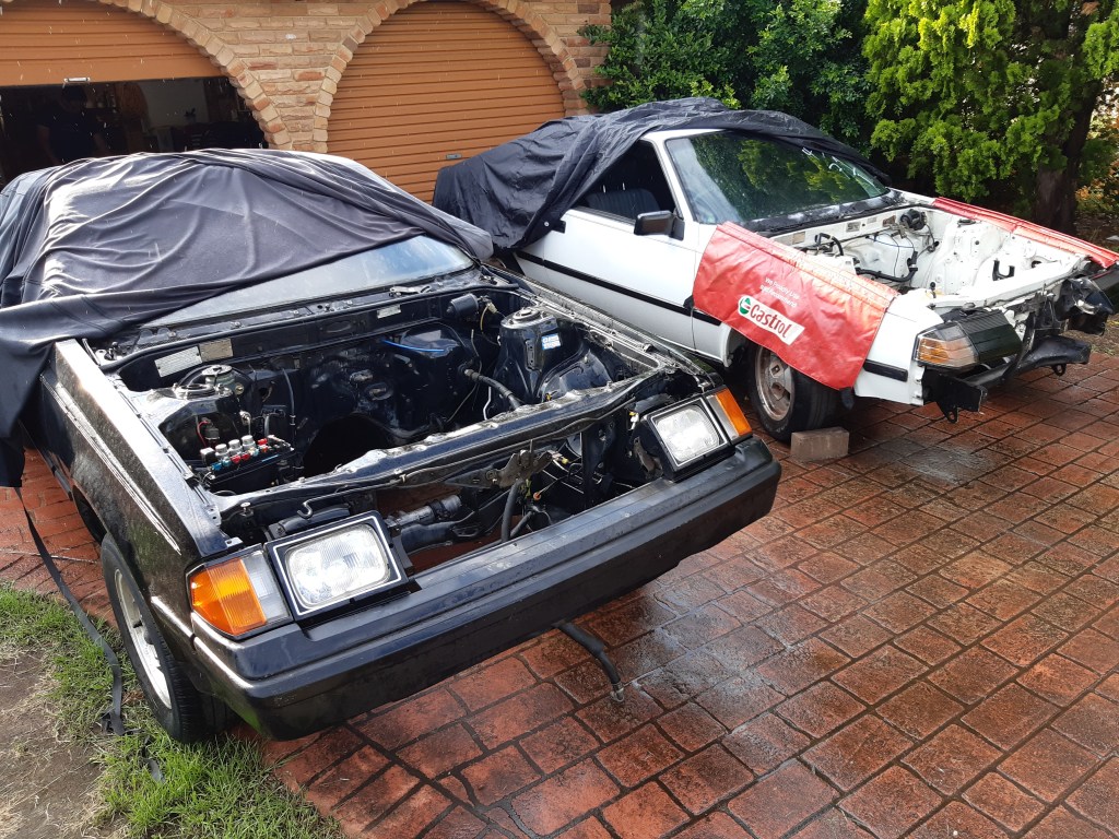
The front lights, bumper and bonnet are interchangable. The RA60 does not have IRS like the white car and going by the differences in the floor pan swapping the IRS sub frame does not look simple.
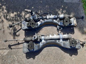
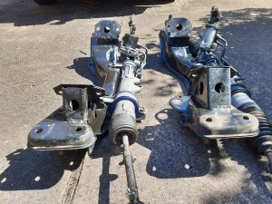

Comparison between the R and S crossmembers. The angle and position of the mounting brackets are different, and the SA63 has a more compact steering rack. I will be using the S steeering rack as I had it recbuilt recently and it is in good condition. Also the clearance for the rack under the sump is tight, even after modifying the sump webbing.


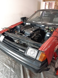
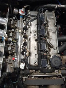
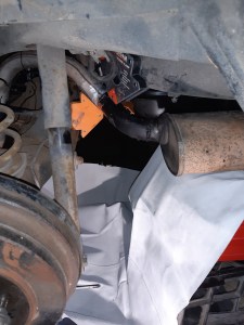
Engine in. Due to the taper of the transmission tunnel and the weight of the j160 I put the engine and transmission in at the same time. for the bellhousing to fit between the tunnel and the crossmember, the rear two crossmember bolts can be removed so it can tilt downwards. The RA60 and SA63 transmission crossmembers are the same so either can be used. The exhaust I was using was originally from this car, but I modified it to fit around the IRS subframe on the other car. I will be changing the exhaust back to fit this car as a temporary measure until I can get a new exhaust made.
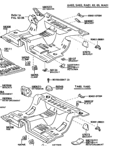
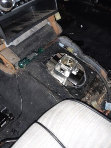
I did not have to cut out a section of the transmission tunnel like last time because the hole on the RA60 is further forward. The position of the shifter itself is the same as before.
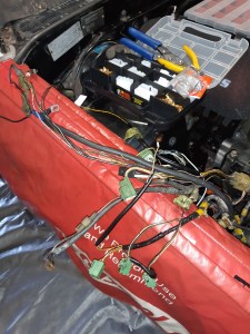
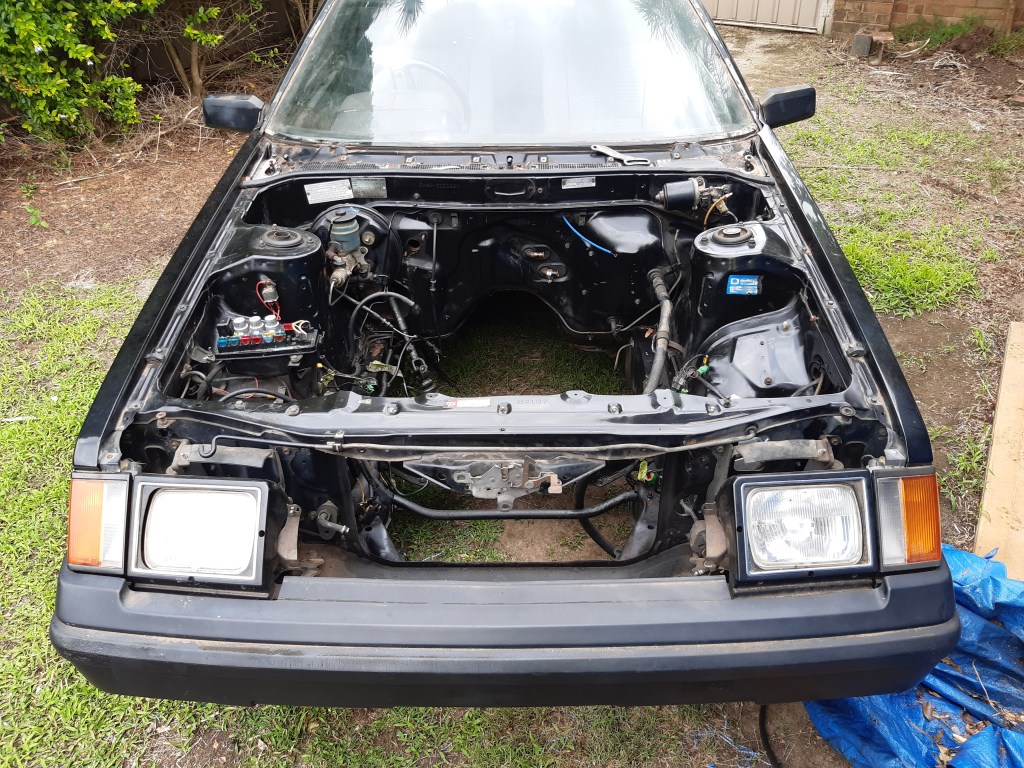
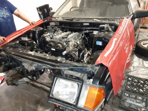
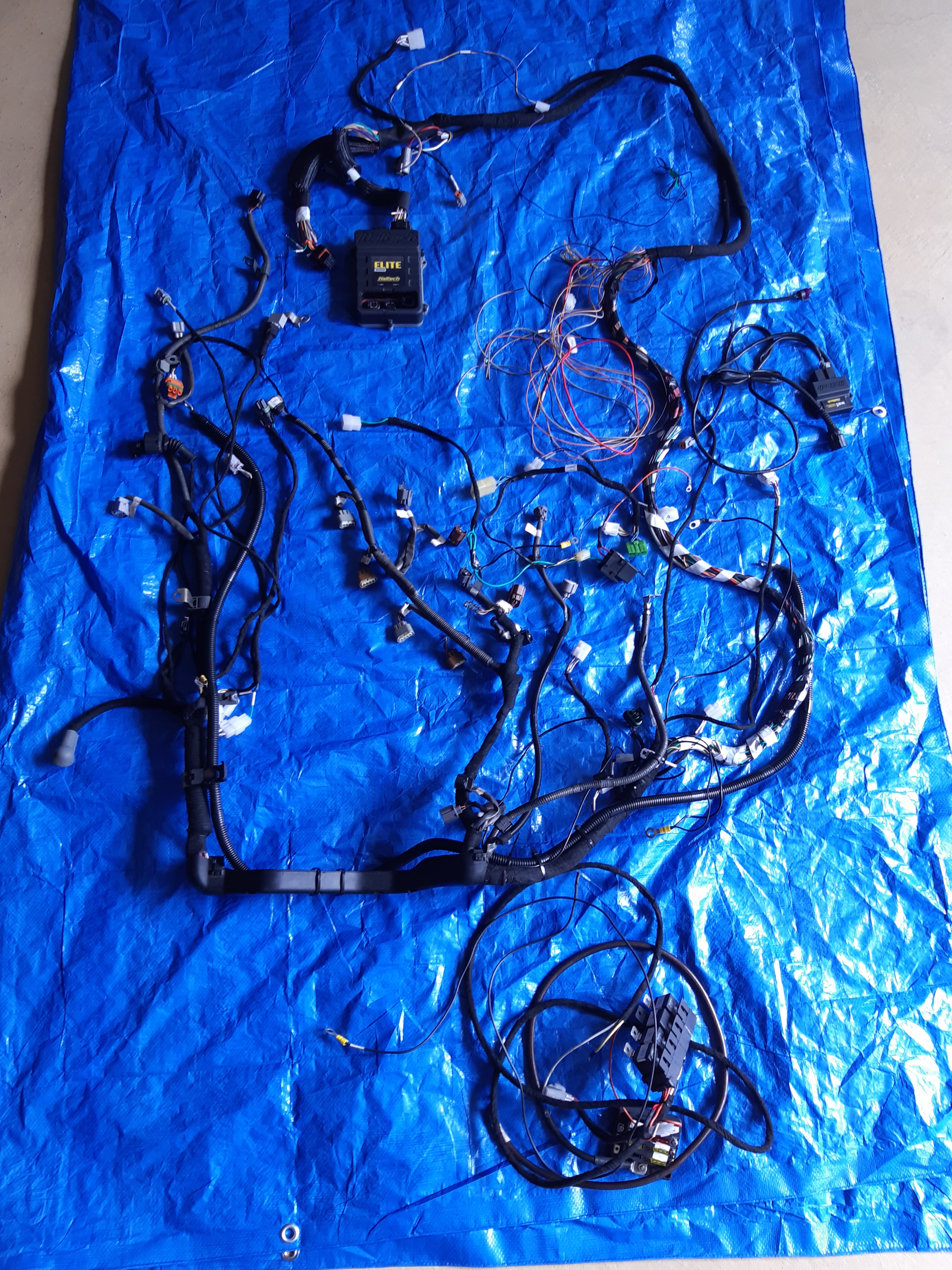
The main issue stopping this from being a straight swap is the wiring. Compared to the 2S, the sensors on the 21R are in a different spot. As is the AC compressor. The battery and main fuse box are also on the opposite side of the engine bay. To fix this problem the harness will be modified
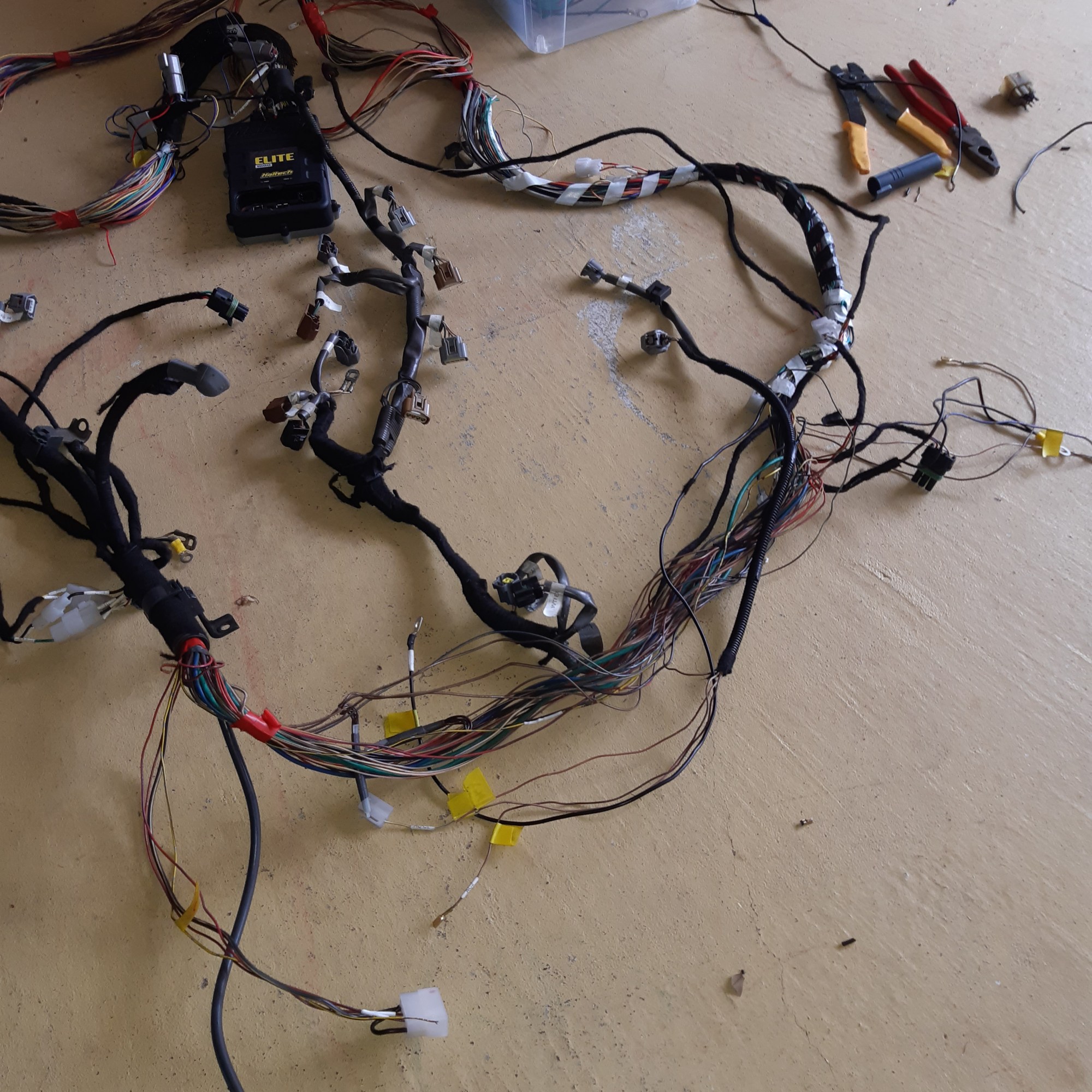

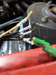
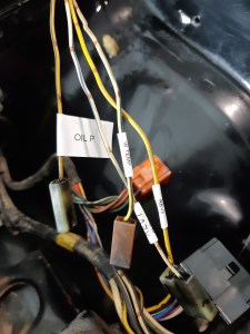
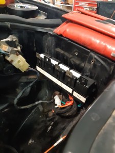
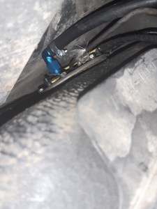
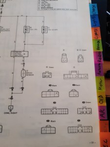
I started by pulling apart the harness and removing unneeded wires. The wires that need to connect to the chassis have been re-routed to the intake side of the harness. All of the connections from the engine harness to the chassis on the drivers side is on an 8 pin plug. This includes the starter motor, reverse switch, oil pressure switch and the battery ground cable for the ECU. The 6 pin plug on the passenger side has the outputs for the tacho signal conditioner, signal ground and the input wire for the exhaust VVTi solenoid which is currently unused.


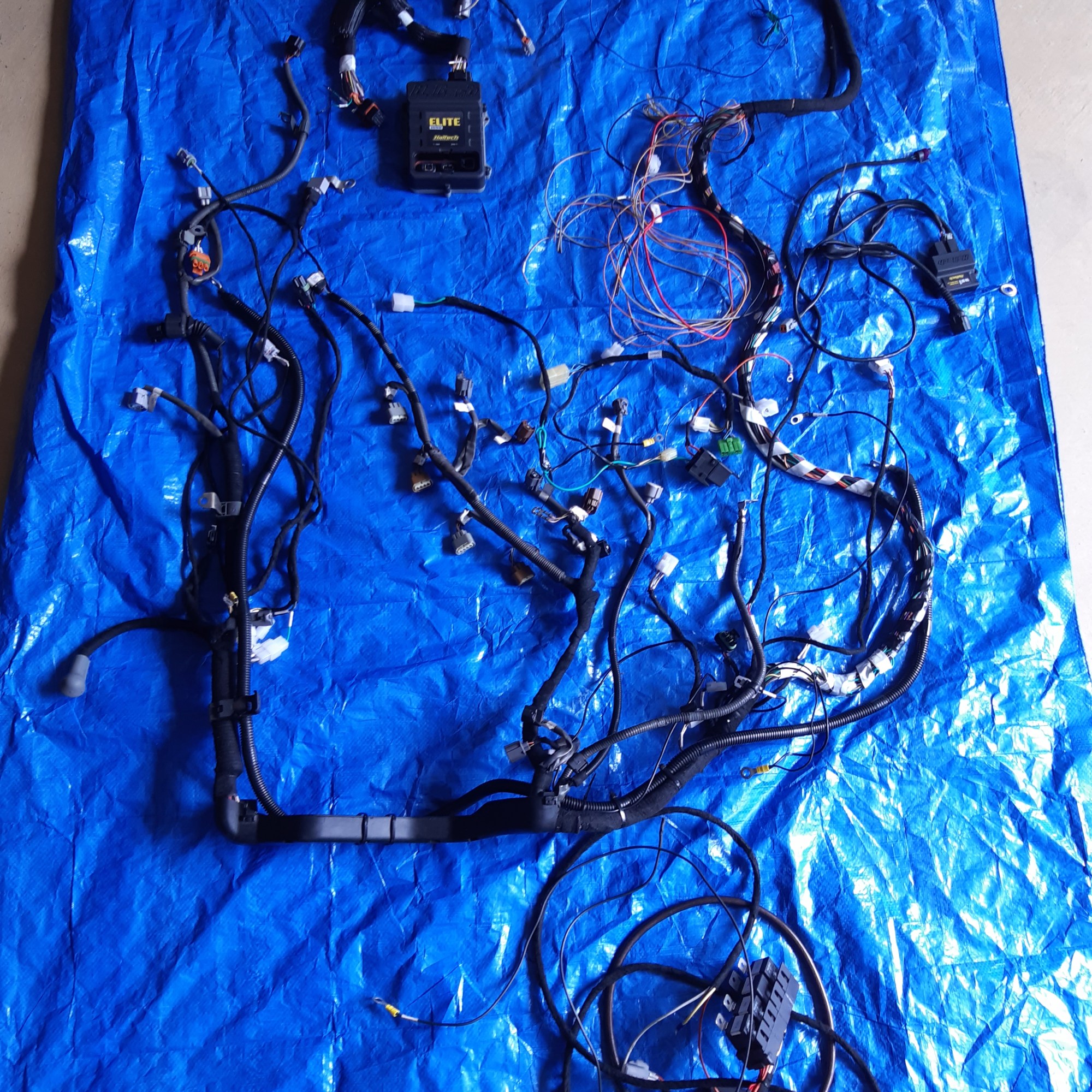
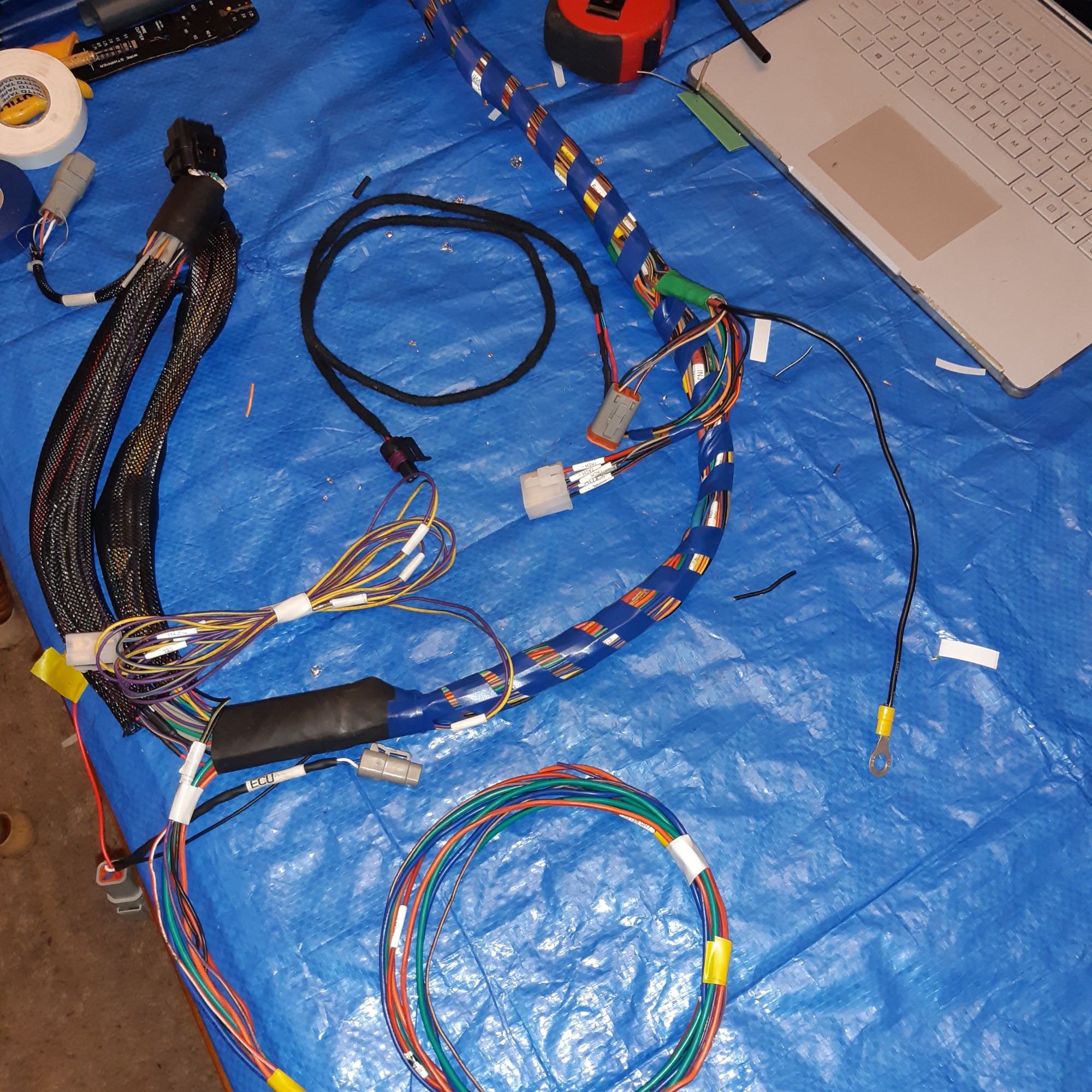
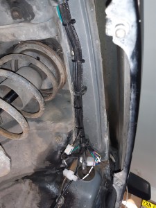
The original wrapping has all been replaced, with tube/tape for the main sections and braid used for the sections with connectors. The Denso plugs for the injectors, ignition coils, cam sensors, alternator, VVTI solenoids, TPS, oil switch and knock sensor have also been replaced with new ones.
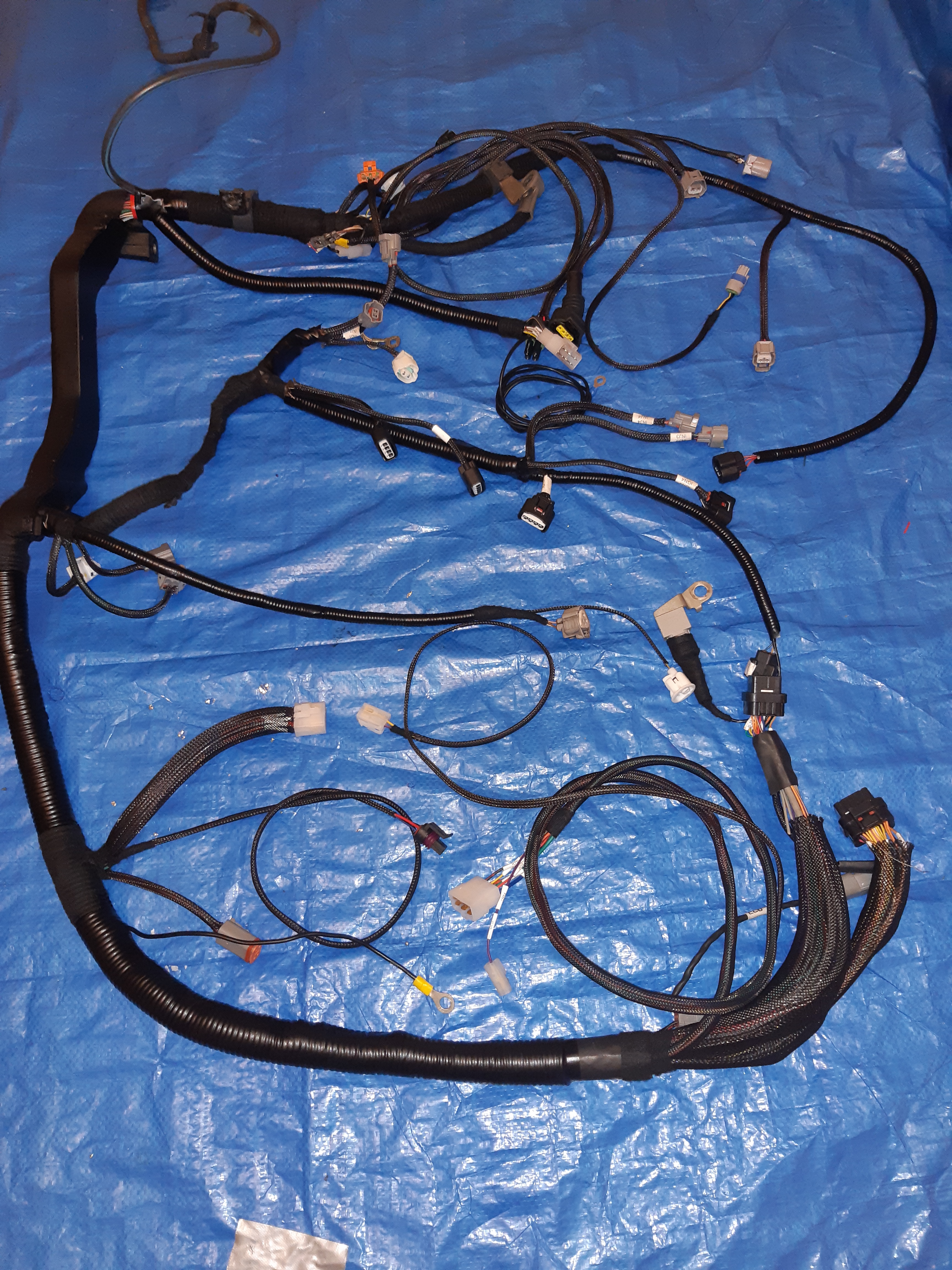

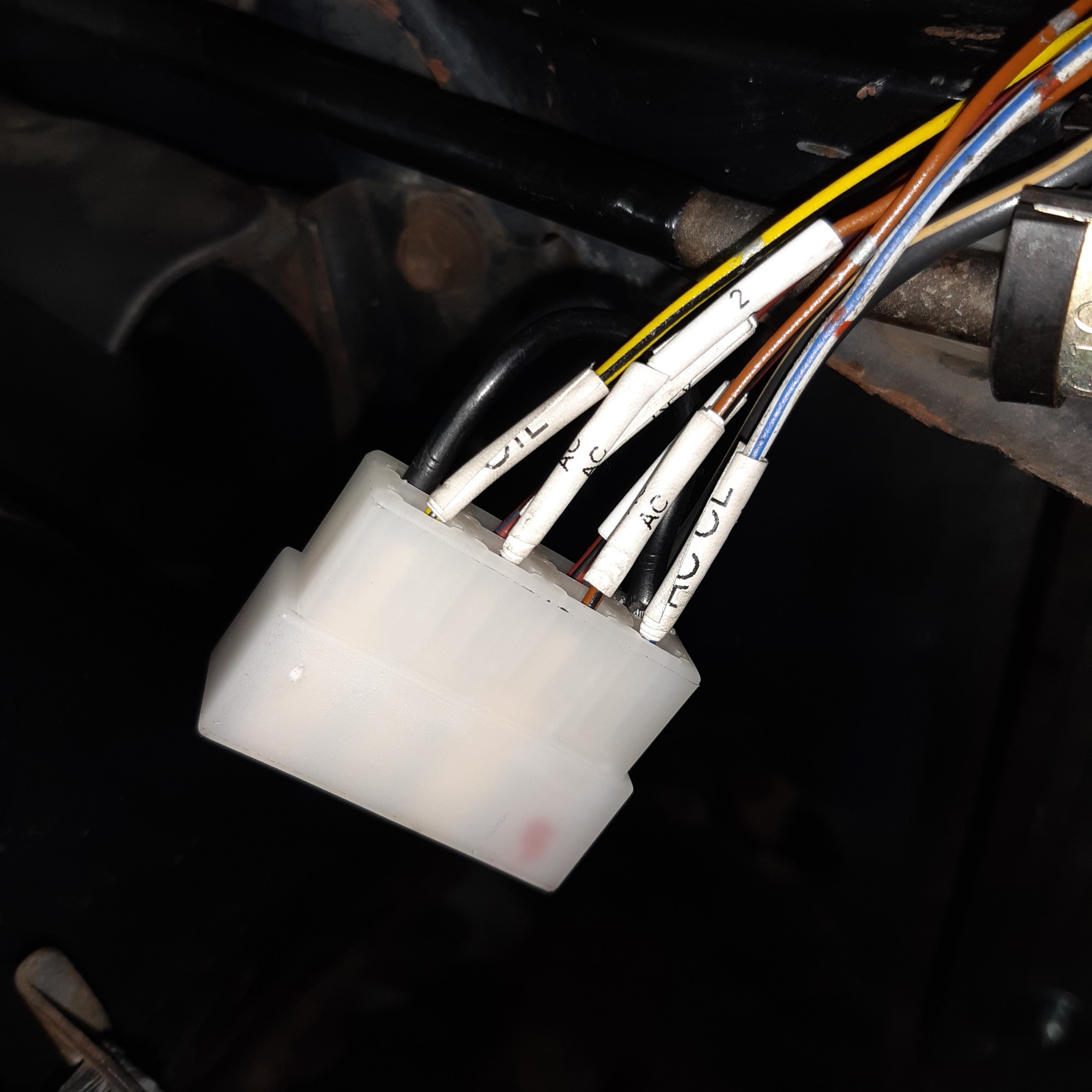
Now that the harness is back on the engine I was able to finish off the chassis side. Only a few big changes are needed, such as the alternator connector on the passenger side, reverse switch, starter and inputs like oil switch, water temp and tachometer.
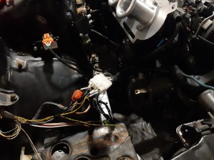
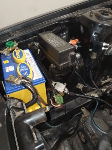
The alternator output cable (+B) was relocated to the drivers side so that it could be connected to the positive battery terminal.
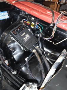
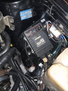
I have relocated the relay block for the Haltech from the passenger kick panel to the engine bay, near the wiper motor. The I/O for alternator, Tachometer, original ignition circuit connect to the chassis on this side. For the original tachometer on the dash cluster to work I will be using a Tacho Ouput Adapter which will condition the signal from the Haltech to an emulated 12v signal that will work with the RA60 dash.

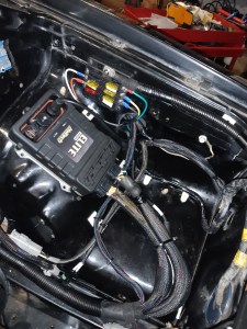
The wiring on the fuse box side has been tidied and re-wrapped. The unneeded parts have been removed, such as the wires for the old 21R vacuum switching valves for idle, emissions, carburettor choke and fuel cut.
Fuel Tank
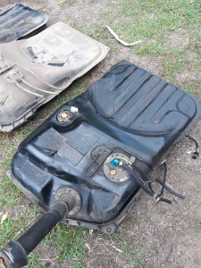
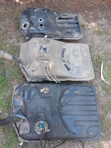
The RA60 fuel tank won’t work with EFI so I put the 22RE fuel tank in that I was using in the old car. Due to differences in the floor pan the tank actually fits better and there is enough clearance on the fuel pump hanger that it doesnt foul on the floor pan.
Exhaust
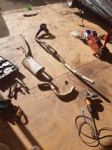
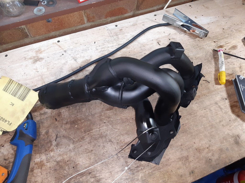
Once the engine has a driveable tune I will be getting a new exhaust made, but for now I’ll be making a temporary one. The RA60 exhaust has been welded back together, as I had to modify it to clear the IRS subframe on the other car. I cut the header flange off and attached a 2-1 collector and joined it to the original down pipe. Not the best set up but it’ll get the engine running.
ITB Calibration
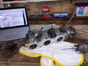
As the ITBS are on a new manifold they need to be re calibrated. I adjusted the throttles in accordance with the 4A-GE 20V service manual (see above link). I am using the original dash pot, with the vacuum disconnected as I found at idle with this setup the dashpot closes completely making the engine stall. I may reconnect it in the future but it is disconnected for now. I am still finding the right value for the throttle gap through trial and error but I’ve found 1.3mm allows for a cold start idle that works (in conjunction with the idle control valve) and at operating temp will idle with the control valve closed, allowing some head room for electrical/AC idle up.
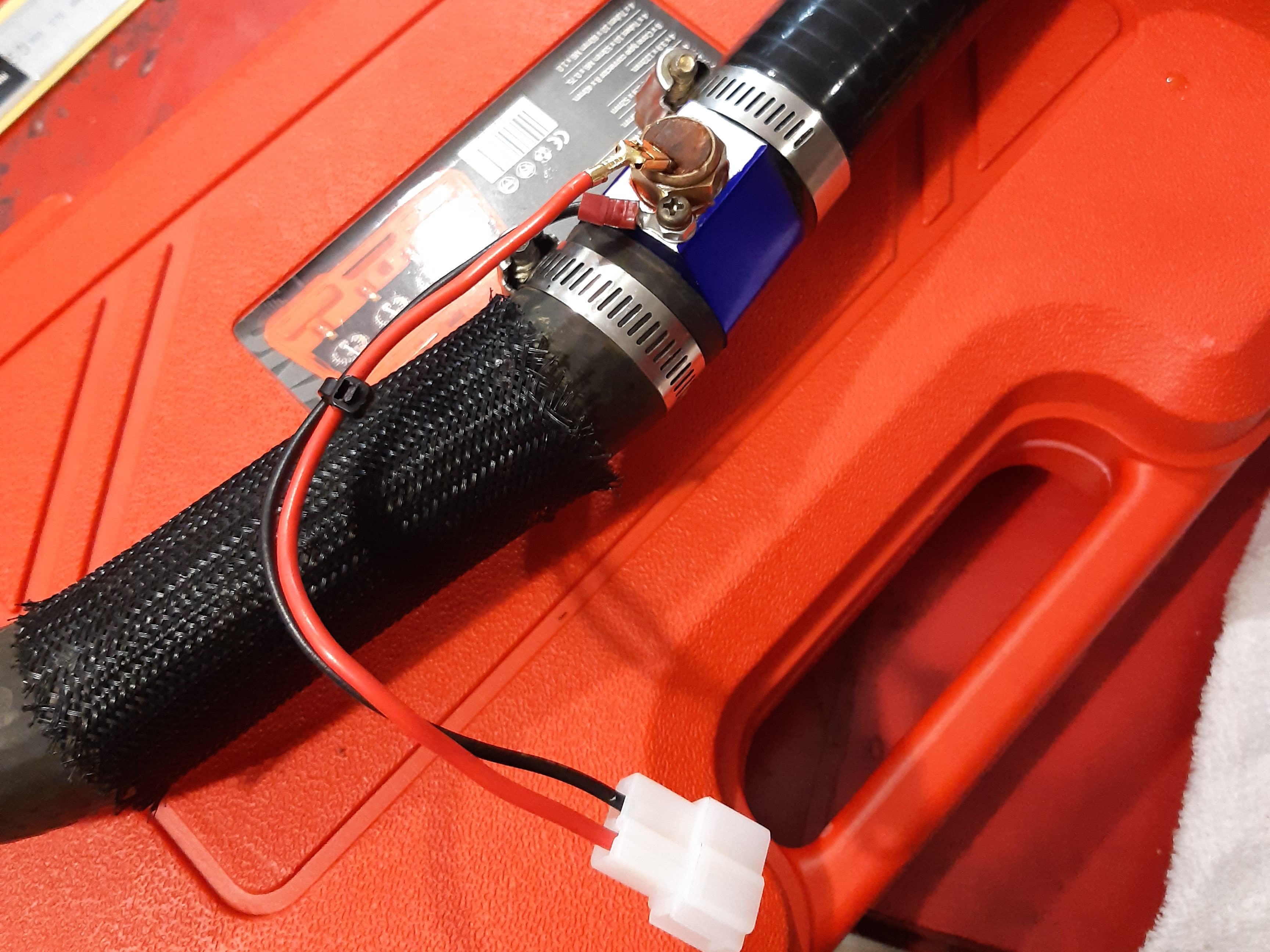
Speed Sensor
Distribution Block
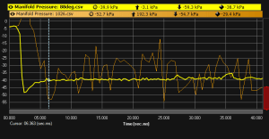
While testing the engine I found that the MAP sensor signal is erratic. The distribution block currently used in the vacuum setup is too small so the vacuum pulses from each cylinder is effecting the MAP readings.
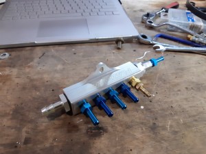
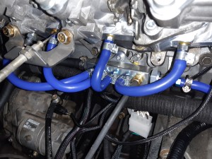
To fix this I am using a Plazmaman vacuum distribution block This has a much larger internal area which will allow for a more stable manifold pressure. The idle control, vacuum hoses for each cylinder, MAP and dashpot/evap are connected. I am not using a vacuum reference for the fuel pressure regulator, as I have it set to a fixed pressure of 60-62 PSI like the original returness fuel system for the BEAMS.
Sensors
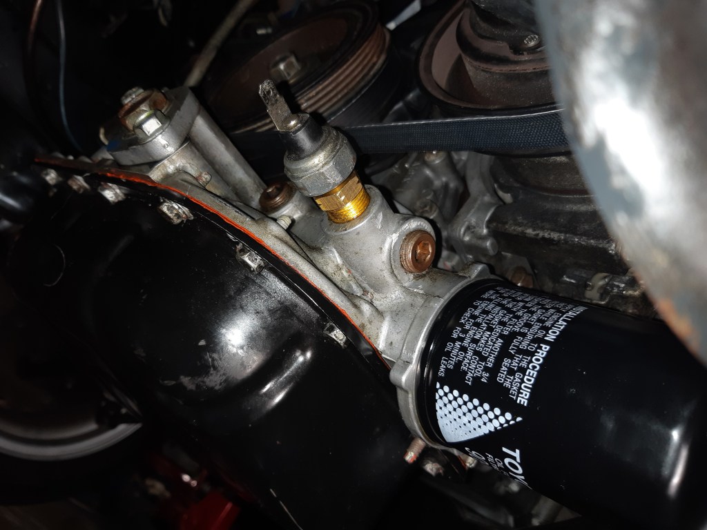
In order for the dash cluster to work properly I had to do some work with the sensors. The Haltech outputs a 5v square wave output for the tacho, so for the signal to be a readable coil negative 12v analog signal I used a Tacho Output Adapter. The voltmeter gets its reading from the positive battery terminal so no changes were needed. The oil switch for the BEAMS works on 5V and is incompatible with the dash so I have plumbed in the original 2S-C oil switch. I’m using a TI 150psi oil pressure sensor with the Haltech, as it was triggering DTCs and sending off the check engine light when I had it wired to the 2S-C oil switch. The 3S-GE coolant temp sensor is also 5V and incompatible with the dash so I am using the original 21R-C temp sender which is plumbed into the top radiator hose.

Looking good. My SA60 with 1UZ and W58 has to have the motor and box put in from underneath. I’m still waiting on my TT14X corona shell to arrive to put my 3SGE Beams etc into. I have a MA46 7.5″ rear end I got from the USA to slot into it if I keep 4 stud, otherwise have a modified MS123 (might be 112) Crown 7.5″ disc rear end to bolt in if I go 5 stud but need to run a 35P wheel. Live axle actually better than the IRS handling wise. Use 6.7″ disc rear from MA45 celica – can beef up with parts from Weir Performance with bigger axles and maxgrip LSD.
LikeLike