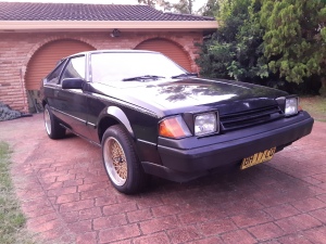
Chassis Swap pt.2

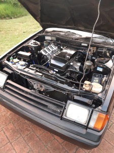
Now that the engine is in the car I can work on getting it running.
Fuel Tank


The RA60 fuel tank won’t work with EFI so I put the 22RE fuel tank in that I was using in the old car. Due to differences in the floor pan the tank actually fits better and there is enough clearance on the fuel pump hanger that it doesnt foul on the floor pan.
Exhaust


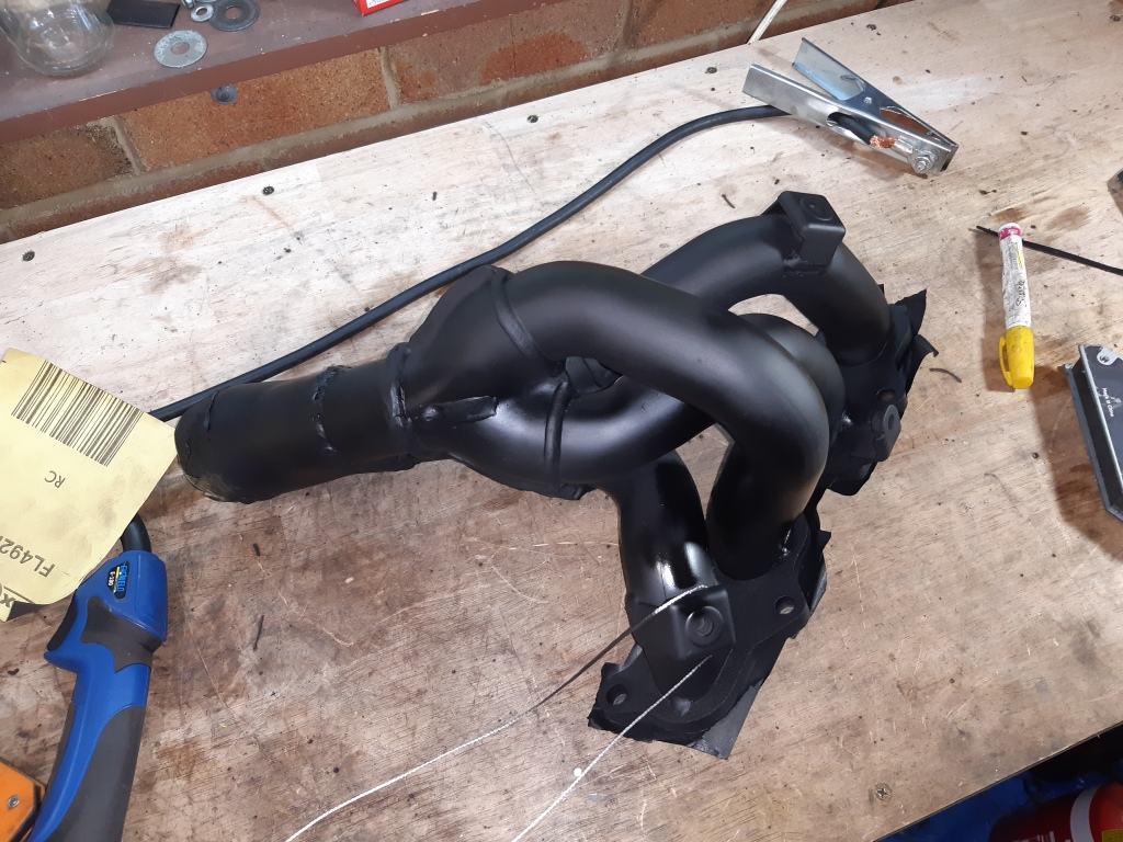
Once the engine has a driveable tune I will be getting a new exhaust made, but for now I’ll be making a temporary one. The RA60 exhaust has been welded back together, as I had to modify it to clear the IRS subframe on the other car. I cut the header flange off and attached a 2-1 collector and joined it to the original down pipe. Not the best set up but it’ll get the engine running.
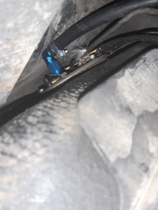
Speed Sensor

In order for the speedometer to work, I had to replace the speed sensor in the J160 gearbox with a mechanical speedo drive. This means that the ECU currently has no speed input.
The RA60 dash cluster does have a speed sensor in it, as part of the original emissions system. However it is a reluctance sensor, not a 5v square wave sensor which is required for speed detection. It may be possible to convert this signal, but I am going to look at other options for now.
ITB Calibration

As the ITBS are on a new manifold they need to be re calibrated. I adjusted the throttles in accordance with the 4A-GE 20V service manual (see above link). I am using the original dash pot, with the vacuum disconnected as I found at idle with this setup the dashpot closes completely making the engine stall. I may reconnect it in the future but it is disconnected for now. I am still finding the right value for the throttle gap through trial and error but I’ve found 1.3mm allows for a cold start idle that works (in conjunction with the idle control valve) and at operating temp will idle with the control valve closed, allowing some head room for electrical/AC idle up.
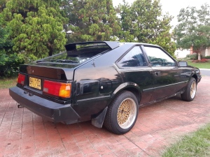


The car is drivable, but completely untuned. I will be working on the tune so that it is drivable as the car still needs to be taken for a new exhaust, and inspections as it is not legally drivable on NSW roads in its current state. I have also ordered parts for the new suspension setup but due to large lead times from the US and other issues I will not be seeing these parts for a while.
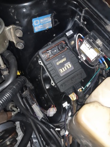
Distribution Block
While testing the engine I found that the MAP sensor signal is erratic. The distribution block currently used in the vacuum setup is too small so the vacuum pulses from each cylinder is effecting the MAP readings.


To fix this I am using a Plazmaman vacuum distribution block This has a much larger internal area which will allow for a more stable manifold pressure. The idle control, vacuum hoses for each cylinder, MAP and dashpot/evap are connected. I am not using a vacuum reference for the fuel pressure regulator, as I have it set to a fixed pressure of 60-62 PSI like the original returness fuel system for the BEAMS.
Sensors


In order for the dash cluster to work properly I had to do some work with the sensors. The Haltech outputs a 5v square wave output for the tacho, so for the signal to be a readable coil negative 12v analog signal I used a Tacho Output Adapter. The voltmeter gets its reading from the positive battery terminal so no changes were needed. The oil switch for the BEAMS works on 5V and is incompatible with the dash so I have plumbed in the original 2S-C oil switch. I’m using a TI 150psi oil pressure sensor with the Haltech, as it was triggering DTCs and sending off the check engine light when I had it wired to the 2S-C oil switch. The 3S-GE coolant temp sensor is also 5V and incompatible with the dash so I am using the original 21R-C temp sender which is plumbed into the top radiator hose.
Related Posts
Categories
