4age 20v ITB’s

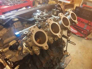
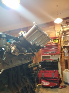
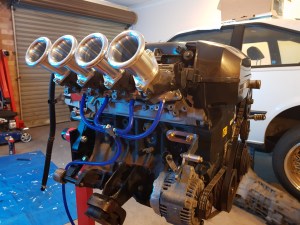
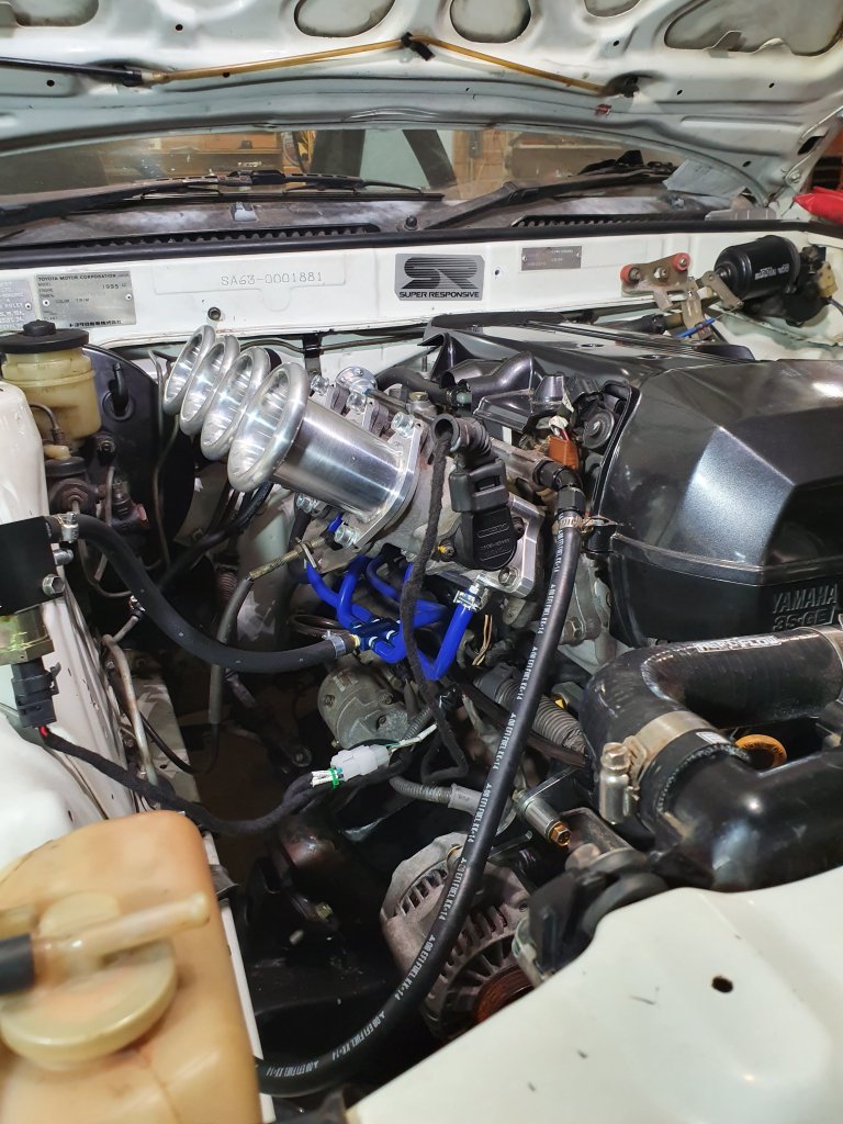
I had originally planned to use the beams intake, but decided that the benifits of changing to an ITB setup was worth the small cost increase These are the ITBs I will be using, from a 4AGE 20V blacktop. the AE111 manifold will not work, so I am using An ITB adapter from SQ Engineering which bolts onto the existing manifold insulator.


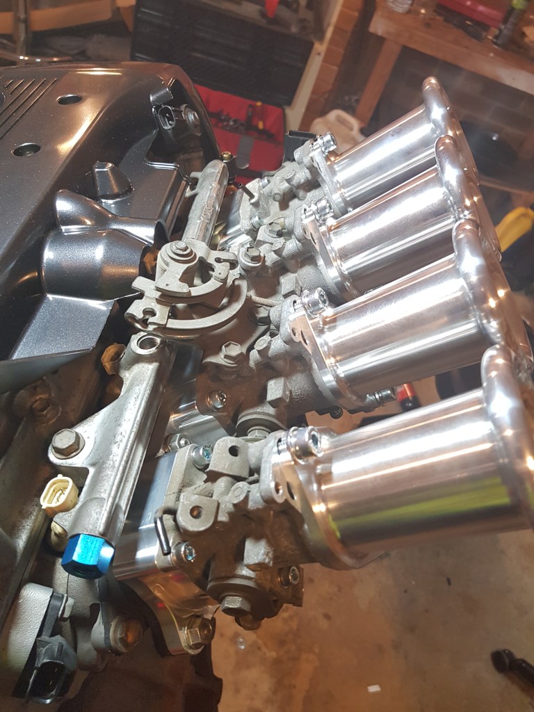
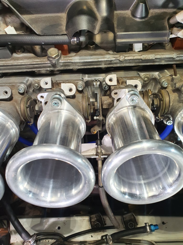
I’m using 100mm velocity stacks, also from SQ Engineering. The AE111 throttle linkage is facing the wrong way as it originally was on a front wheel drive engine. it is also on top of where the banjo fitting for the fuel rail is so it will have to be changed to a downpull throttle linkage.The downpull throttle linkage will allow the throttle cable to be fed from underneath the throttle body set up, out of the way of the fuel lines and air filter.
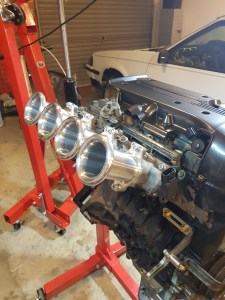

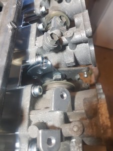
Fitted the new throttle linkage. This solution allows the throttle cable to be routed from underneath. The original SA63 throttle cable is too short to reach, as the original carby throttle was closer to the firewall. A new throttle cable is needed. I need to get measurements but a cable from a larger car with a 7mge or 1jz may work.
MAP Sensor
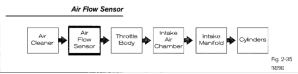
For the engine to run, it needs an input from the throttle and a second input which acts as a feedback loop. This allows for the fuel trim to be adjusted depending on load conditions. the first input is the throttle position sensor which tells the ECU exactly how open or closed the throttles are. The signal for the feedback loop comes from the mass air flow sensor.
This sensor measures the amount of air drawn into the engine. This is mapped against throttle position sensor to adjust fuel trim. This works for a regular throttle body, but with ITB’s the velocity stacks are open to the air so it is impossible to measure air flow without a plenum. For this intake setup, a manifold absolute pressure (MAP) sensor is used instead.
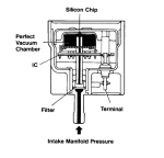
A MAP sensor monitors changes in the manifold pressure, which will vary depending on engine load. This value is used to measure intake air pressure. As this is measuring the pressure downstream from the throttle bodies it will work with the ITB’s

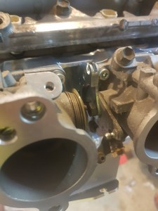
All four throttles have been plumbed with a vacuum line into a distributor block, which is then fed to the MAP sensor in the Haltech ECU.
Throttle Cable

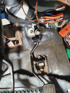
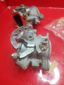
The original throttle cable from the 2S is too short and does not reach the linkage for the ITB’s. I had a look at some old Toyotas at the wrecking yard and found one that would fit from a 1989 SV21 Camry. The only modification required was to swap the bracket from the old cable as the throttle stop was in the wrong position.
Fuel Rail
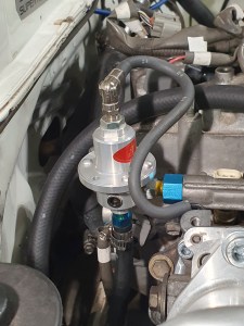
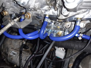
I have replaced the existing fuel hose which uses a banjo fitting, to a M12 1.25 to 45° 5/16 barb fitting connected to the front of the fuel rail. The original setup was designed to be routed at the back of the engine but there was no room with this engine bay layout.
Idle Control
I had to make some changes to the engine harness for the idle control valve. I had originally planned to use a two wire bimetallic type valve, but I will be using a Screw-in style idle control valve. This valve uses a stepper motor which allows for greater control over the idle speed. This valve requires four ECU outputs to be driven, so I had to reallocate stepper outputs STEP1-4 and change the harness. STEP1-4 have been connected to a plug on the drivers side of the harness, near where the idle control valve will be mounted.

The idle control valve inlet is connected 3/8 hose that draws in air from the air filter backing plate. It feeds into the vacuum distribution block.
ITB Calibration
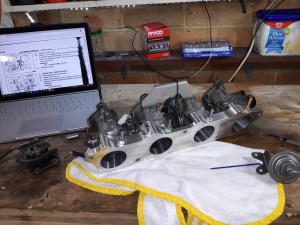
As the ITBS are on a new manifold they need to be re calibrated. I adjusted the throttles in accordance with the 4A-GE 20V service manual (see above link). I am using the original dash pot, with the vacuum disconnected as I found at idle with this setup the dashpot closes completely making the engine stall. I may reconnect it in the future but it is disconnected for now. I am still finding the right value for the throttle gap through trial and error but I’ve found 1.3mm allows for a cold start idle that works (in conjunction with the idle control valve) and at operating temp will idle with the control valve closed, allowing some head room for electrical/AC idle up.
Distribution Block
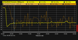
While testing the engine I found that the MAP sensor signal is erratic. The distribution block currently used in the vacuum setup is too small so the vacuum pulses from each cylinder is effecting the MAP readings.
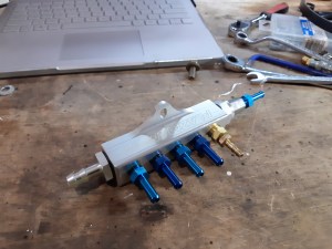
To fix this I am using a Plazmaman vacuum distribution block This has a much larger internal area which will allow for a more stable manifold pressure. The idle control, vacuum hoses for each cylinder, MAP and dashpot/evap are connected. I am not using a vacuum reference for the fuel pressure regulator, as I have it set to a fixed pressure of 60-62 PSI like the original returness fuel system for the BEAMS.
Categories
